
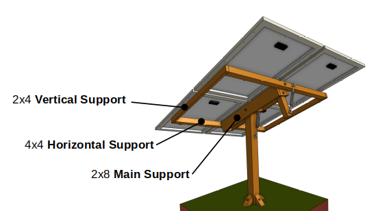
Upper Structure
Cut Lengths Worksheet
Use the worksheet below to calculate board cut lengths relative to the length and width of the solar panels.
|
Board Size |
Name |
Expression for Cut Length |
Length |
|
2x8 |
Main Support |
(Solar Panel Length) - 2.5in = |
|
|
4x4 |
Horizontal Support |
(Solar Panel Width) x 2 - 2in = |
|
|
2x4 |
Vertical Support |
(Solar Panel Length) + 4.5in = |
|
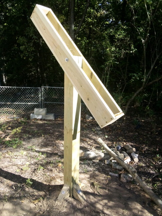
Main Support
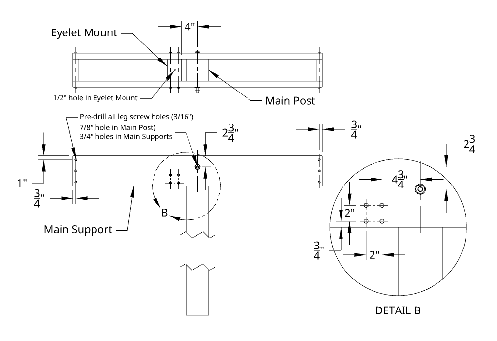
Drill a 7/8” hole through the Main Post, 1 ¾” from the top. The large 7/8” diameter allows the design to tolerate a hole that is not perfectly level (up to +/- 1/8” variation at both ends).
Using 2x8 boards, cut two Main Support boards to the length written on the worksheet (above). Drill an 11/16” or 3/4” hole near the center of each Main Support, 2 ¾” from the top edge. Attach the main supports to the main post using 5/8-11x10 hardware. Tighten until the Main Support can be moved by hand with resistance.
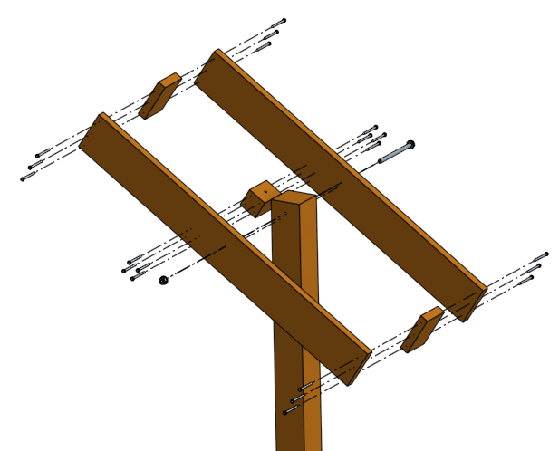
Cut two 5 ½” end pieces for the Main Support from 2x8 fragments. Pre-drill 3/16” holes through the Main Support boards into the end pieces and attach using 5/16x4 leg screws.
Cut a 5 3/8” section of 4x4 post. Drill a ½” hole through the middle of a side of the 5 3/8” section for attaching an eyelet. Pre-drill 3/16” holes through the Main Support boards into the ends of the section and attach using 5/16x4 leg screws.
Horizontal & Vertical Supports
Cut two 4x4 post sections for Horizontal Supports to the length written on the worksheet (section 4.1). Cut one 18” section of 4x4 post for the Pivot Arm.
Drill 9/16” holes through the center of a side of the Horizontal Support sections. Drill a 9/16” hole in each end pieces, centered and 2” below the top edge. Drill one additional hole in the rear end piece (away from the direction of the sun) 1 ½” above the bottom edge. Use the end piece holes to template holes in the Pivot Arm with the top of the Pivot Arm flush with the top of the rear end piece.
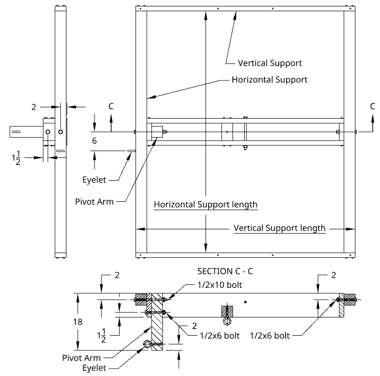
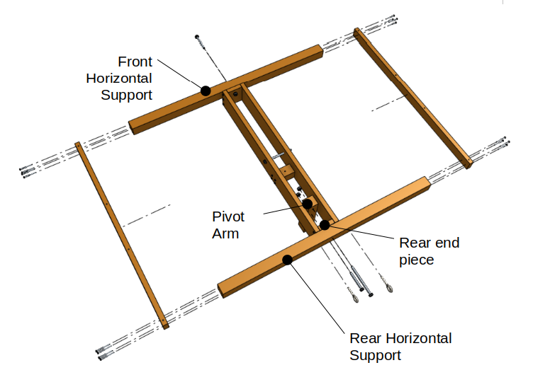
Attach the front Horizontal Support with 1/2x6 hardware. Attach the rear Horizontal Support and Pivot Arm to the upper hole using 1/2x10 hardware and secure the Pivot Arm to the lower hole using 1/2x6 hardware. Attach the Vertical Supports using 5/16x4 leg screws, pre-drilling 3/16” holes.
Solar Panel Mounts
Refer to the solar panel datasheet to determine the Panel Footprint Vertical and Panel Footprint Horizontal distances.
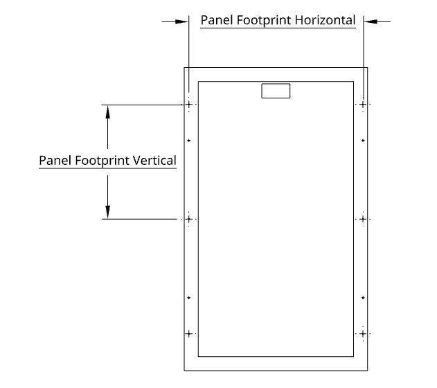
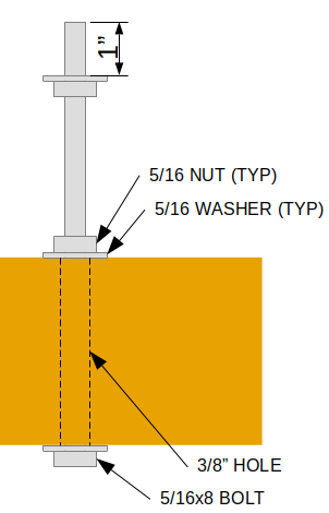
Drill 3/8” holes in each Vertical Support at 1 ½” from each end and at Panel Footprint Vertical + 1 ½” from each end. After drilling holes in the Vertical Support, drill 3/8” holes at the Panel Footprint Horizontal distance, toward the middle of the Horizontal Support (Figure 13).
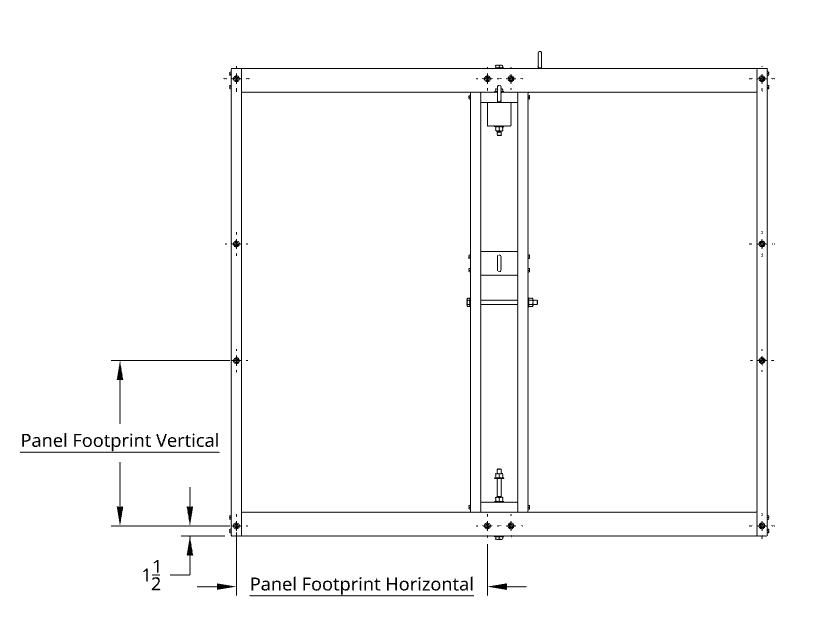
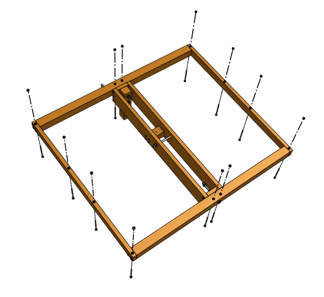
Prepare mount points for the solar panels by attaching one 5/16x8 bolt, three washers, and two nuts at each of the 3/8” holes drilled as shown in Figure 16. Leave approximately 1 inch of threaded length between the upper washer and end of the bolt. Leave the nuts at the wood supports finger tight so that the mount has some flexibility.
Attach each solar panel to a set of 3 mount points on the Horizontal and Vertical Supports. After installing a solar panel onto a set of mount points, fasten the panel to the mount points with 3 nuts and washers and tighten nuts at the solar panel and at the wood supports. After all solar panels have been mounted, adjust nuts as necessary to align each solar panel with respect to the others.
Attaching Solar Panels
Rotate the Upper Structure until one corner is near ground level. Gently place a panel onto three (3) mount points, and fasten with a washer, nut, and lock-washer.
Repeat for each panel at each corner. After each repositioning of the Upper Structure, it may helpful to lock the Upper Structure in place with a tie-down strap.
Electrical Installation
Attach the breaker enclosure to the Main Post.
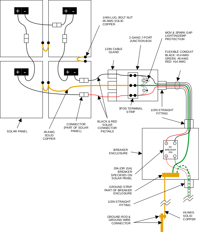
Attach the 7-port junction box to the lower side of the Main Support structure.
Install flexible conduit and conduit connectors between the breaker enclosure and junction box, allowing enough slack for rotation of the Main Support structure.
If the solar panels are exposed to light and connected together in series (or even individual, depending on panel voltage), solar panel wires may conduct high voltage current that could be dangerous. Typically it's best to wait until all electrical components and wiring have been installed before connecting the solar panels.
Attach ground wiring between a terminal strip inside the junction box and the frames of each solar panel (see schematic below). Run ground wire from the terminal strip in the junction box through the conduit and attach to ground strip inside the breaker enclosure. Run bare ground wire from the ground strip out of the breaker enclosure and down the Main Post to a ground rod.
Install a 20A (or 15A, depending on what is required by the solar panel datasheet) inside the breaker enclosure. Install power wiring and lightning/EMP protection between terminal strip lugs and the breaker. Install power and ground wiring between the breaker inside the breaker enclosure and down through interconnect conduit (attached to the breaker enclosure) to the rest of the solar power system (not shown).
No Comments