Solar Panel Arrays
4 Panel 2 Axis
Introduction
Major Axis
The connection between the Main Supports (see Upper Structure) and the Main Post becomes the Major Axis, which allows angle adjustment for the elevation angle of the Sun, throughout the year.
Minor Axis
If the major axis has been adjusted so that the panel array orientation is normal to the Sun at noon, then the minor axis can be used to follow the Sun throughout the day from sunrise to sunset. Automated systems can be installed to follow the Sun, or the minor axis can be adjusted manually when there is a need for maximum power.
Conforming to Non-Ideal Conditions
Often solar panels must be mounted in less than ideal locations, such as a location that receives shade during a portion of daylight. On top of that, peak power usage may not coincide with peak solar power (e.g. peak power usage may be disproportionately higher in the evening vs. morning). A minor axis can help to optimize solar power through either dynamic Sun-following or static positioning to maximize power absorption at a certain time of day other than noon.
Material List
| QTY (EA) | QTY (BULK) | PN | Vendor | DESCRIPTION | COST (EA) | COST (BULK) | EXT (EA) |
| General Mechanical | |||||||
| 4 | 1 | Leg Screw, 5/8x8 | $0.00 | $0.00 | |||
| 1 | 1 | Bolt, 5/8x10 | $0.00 | $0.00 | |||
| 6 | 1 | Washer, 5/8 | $0.00 | $0.00 | |||
| 1 | 1 | Bolt, 1/2x10 | $0.00 | $0.00 | |||
| 2 | 1 | Bolt, 1/2x6 | $0.00 | $0.00 | |||
| 36 | 45 | Leg Screws, 5/16x4 | $0.00 | $0.00 | |||
| 2 | 1 | Turn Buckle, 18” | $0.00 | $0.00 | |||
| 1 | Eyelet, 3/8x8 | $0.00 | $0.00 | ||||
| 3 | Eyelet, 3/8x6 | $0.00 | $0.00 | ||||
| 4 | Washer, 3/8 | $0.00 | $0.00 | ||||
| 12 | Bolt, 5/16x | $0.00 | $0.00 | ||||
| 1 | 6x6 Post, 8ft length | $0.00 | $0.00 | ||||
| 4 | 4x4 Post, cut to 24” length, angled 45° | $0.00 | $0.00 | ||||
| 4 | 5/8x8 Leg Screw | $0.00 | $0.00 | ||||
| 4 | 5/8 Washer | $0.00 | $0.00 | ||||
| 1 or 8 | 4x8x16 Concrete Block (quantity 1 for Type I base, quantity 8 for Type II base) | $0.00 | $0.00 | ||||
| 3 | 1 | PDB77550GY | TayMac | 2-Gang Weatherproof 7-Outlet Electrical Box | $11.98 | $35.94 | $35.94 |
| 1 | 1 | B0983ZS2WG | Amazon | 2-pole Breaker | $15.98 | $15.98 | $15.98 |
| 1 | 1 | 1001753748 | Amazon | Min Breaker Box | $17.99 | $17.99 | $17.99 |
| 4 | 100 | 4105012100 | HYDROMAXX | 1/2in Flexible PVC Conduit (100ft) | $78.77 | $78.77 | $3.15 |
| 3 | 20 | 58133657 | Southwire | 1/2in Liquidtight Fitting Straight | $27.27 | $27.27 | $4.09 |
| 1 | 1 | 615880UPC | ERICO | 5/8x8’ Copper Ground Rod | $13.60 | $13.60 | $13.60 |
| 1 | 1 | 65176440 | Southwire | 5/8 Ground Rod Clamp | $2.97 | $2.97 | $2.97 |
| 25 | 25 | 10665803 | Southwire | #6 AWG Stranded Bare Copper Wire (50ft) | $24.10 | $24.10 | $24.10 |
| 5 | 10 | E977DC | Carlon | 1/2in PVC Conduit Clamps | $1.25 | $1.25 | $0.63 |
| 6 | 1 | V150LA20CP | Littelfuse | MOV 150V(nom) 395V(clamp) | $1.28 | $7.68 | $7.68 |
| 4 | 1 | 2035-20-B | Bourns | Spark Gap Surge Arrestor 200V | $1.00 | $4.00 | $4.00 |
| 3 | 10 | LPCG50-10 | Arlington | 1/2in Cable Gland, .200-.472 | $2.00 | $2.00 | $0.60 |
| $0.00 | $0.00 | ||||||
| $0.00 | $0.00 | ||||||
| $0.00 | $0.00 | ||||||
| $0.00 | $0.00 | ||||||
| $0.00 | $0.00 | ||||||
| TOTAL | $25.00 | $231.55 | |||||
Base Structure
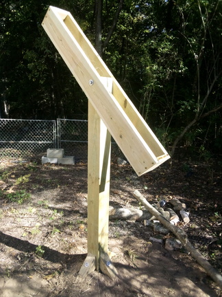
Simple Buried Base

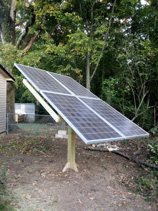
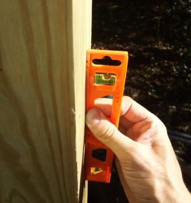
Dig a 2-3ft post hole and insert a 6x6 8ft post. Refill with dirt while checking the angle of the post with a vertical level. The post should lean slightly away from the direction of sunlight (Figure 3.1), but side to side the post should be kept as vertical as possible. This is to account for gradual settling forward in the direction of sunlight, since the center of gravity of the solar panels sits slightly forward of the center of the post.
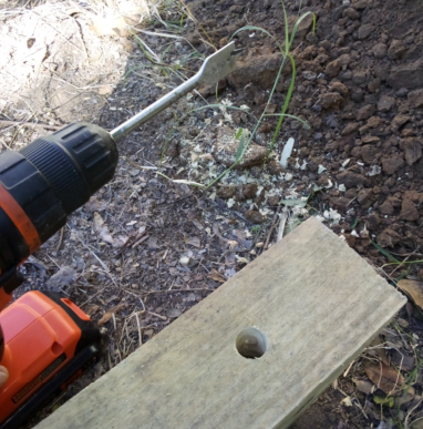
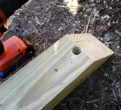
Cut four (4) sections of 4x4 post, 24in length, angled 45deg on one end. Drill a 3/4in through-hole on the longest face, 4in from the angled end.
Dig a 12in square and 12in deep hole centered about 18in from the main post, toward the direction of sunlight.
Remove additional dirt as necessary to allow one of the 24in angled post sections to be held against the main post, angled end about 6in above ground.
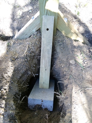
Arrange dirt to support the 16x8x4 concrete block at a 45deg angle centered and in tight contact with the bottom end of the 24in section. Reevaluate the vertical angle of the post and ensure that there is a slight angle rearward, even when applying pressure to the post forward. If necessary, apply rearward pressure to the post (releasing pressure against the block) while packing additional dirt under the block.
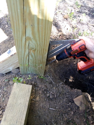
Use the pre-drilled 3/4in hole in the section to template a 1/2in hole to about 4.5in depth into the main post and fasten the 24in section to the main post using a 5/8 leg screw and washer.
The main post is firmly held vertical or a very slight rearward angle (away from direction of Sun), even when applying some forward pressure. Replace dirt and pack firmly.
Dig three 12in post holes about 17in away from each of the other faces of the main post and remove dirt as necessary to allow the remaining 24in sections to be similarly fastened to the main post using 5/8 leg screws and washers (Figure 3.6). Recheck the vertical angle after each 24in section is attached. Refill the holes and pack firmly.
Concrete Footing Base
Concrete footings can be used to eliminate ground contact with wood. 12in diameter concrete footings are recommended with depths of at least 24in.
Angle the 4x4 post sections 45deg on both ends. Like the Simple Base (above), drill a 3/4in through-hole on one end for attachment to the Main Post.
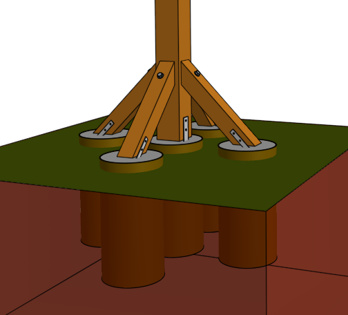
Dig five (5) clearance holes for 12in diameter, 24in depth, concrete molds, spaced 18in (center to center), arranged in a cross pattern. Replace dirt around the outside of the molds and pack gently.
Fill molds with concrete. Embed a 6x6 post anchor in the wet concrete of the middle footing and 4x4 post anchors in the wet concrete of the outer footings. Angle the 4x4 post anchors 45° (anchors may need to be held in position until concrete sets).
Fasten the main 6x6 8ft post to the center post anchor using two 1/2x7 bolts, washers, lock-washers, and nuts. Use the post anchor to template 5/8 holes in the main post. Fasten the 30in angled post sections between the main post and outer post anchors. Use the pre-drilled 3/4in holes in the 30in sections to template 1/2in, 4.5in depth, holes in the main post and fasten with 5/8x8 leg screws. Use the 4x4 post anchors to template 5/8 holes and fasten using 1/2x5 hardware.
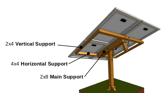
Upper Structure
Cut Lengths Worksheet
Use the worksheet below to calculate board cut lengths relative to the length and width of the solar panels.
|
Board Size |
Name |
Expression for Cut Length |
Length |
|
2x8 |
Main Support |
(Solar Panel Length) - 2.5in = |
|
|
4x4 |
Horizontal Support |
(Solar Panel Width) x 2 - 2in = |
|
|
2x4 |
Vertical Support |
(Solar Panel Length) + 4.5in = |
|
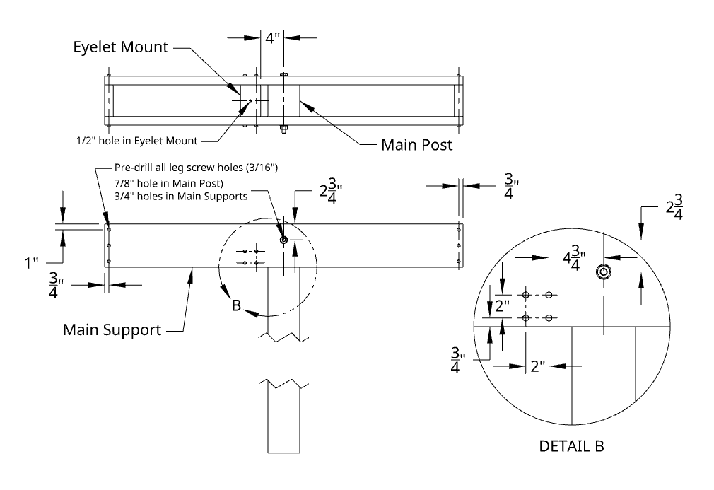
Main Support
Drill a 7/8” hole through the Main Post, 1 ¾” from the top. The large 7/8” diameter allows the design to tolerate a hole that is not perfectly level (up to +/- 1/8” variation at both ends).
Using 2x8 boards, cut two Main Support boards to the length written on the worksheet (above). Drill an 11/16” or 3/4” hole near the center of each Main Support, 2 ¾” from the top edge. Attach the main supports to the main post using 5/8-11x10 hardware. Tighten until the Main Support can be moved by hand with resistance.
Cut two 5 ½” end pieces for the Main Support from 2x8 fragments. Pre-drill 3/16” holes through the Main Support boards into the end pieces and attach using 5/16x4 leg screws.
Cut a 5 3/8” section of 4x4 post. Drill a ½” hole through the middle of a side of the 5 3/8” section for attaching an eyelet. Pre-drill 3/16” holes through the Main Support boards into the ends of the section and attach using 5/16x4 leg screws.
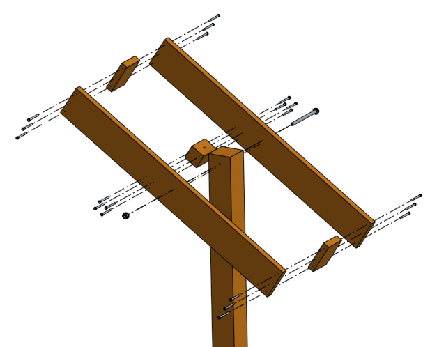
Horizontal & Vertical Supports
Cut two 4x4 post sections for Horizontal Supports to the length written on the worksheet (section 4.1). Cut one 18” section of 4x4 post for the Pivot Arm.
Drill 9/16” holes through the center of a side of the Horizontal Support sections. Drill a 9/16” hole in each end pieces, centered and 2” below the top edge. Drill one additional hole in the rear end piece (away from the direction of the sun) 1 ½” above the bottom edge. Use the end piece holes to template holes in the Pivot Arm with the top of the Pivot Arm flush with the top of the rear end piece.
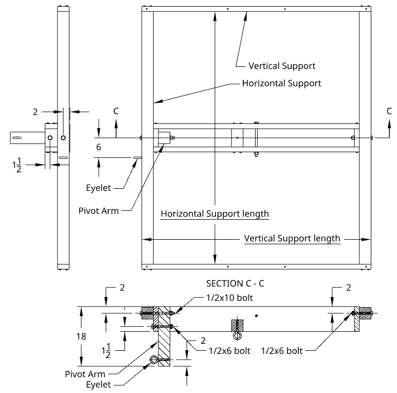
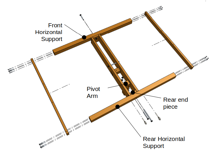
Attach the front Horizontal Support with 1/2x6 hardware. Attach the rear Horizontal Support and Pivot Arm to the upper hole using 1/2x10 hardware and secure the Pivot Arm to the lower hole using 1/2x6 hardware. Attach the Vertical Supports using 5/16x4 leg screws, pre-drilling 3/16” holes.
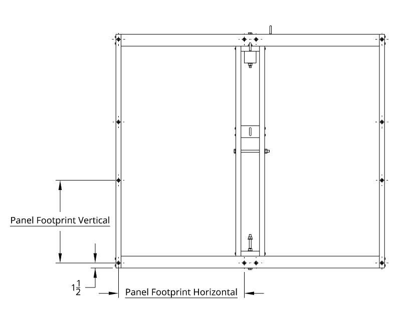
Solar Panel Mounts
Refer to the solar panel datasheet to determine the Panel Footprint Vertical and Panel Footprint Horizontal distances.
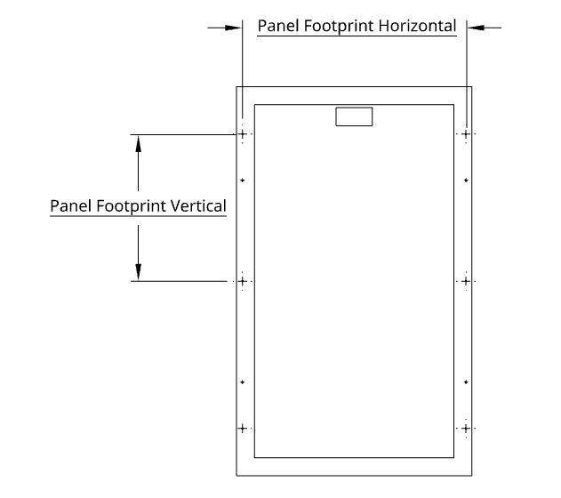
Drill 3/8” holes in each Vertical Support at 1 ½” from each end and at Panel Footprint Vertical + 1 ½” from each end. After drilling holes in the Vertical Support, drill 3/8” holes at the Panel Footprint Horizontal distance, toward the middle of the Horizontal Support (Figure 13).
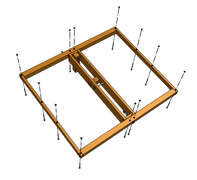
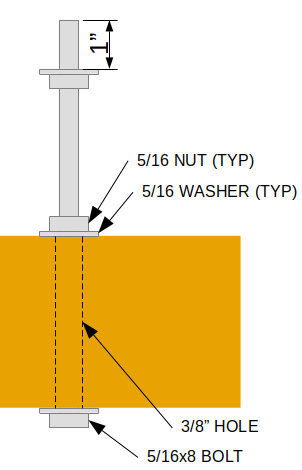
Prepare mount points for the solar panels by attaching one 5/16x8 bolt, three washers, and two nuts at each of the 3/8” holes drilled as shown in Figure 16. Leave approximately 1 inch of threaded length between the upper washer and end of the bolt. Leave the nuts at the wood supports finger tight so that the mount has some flexibility.
Attach each solar panel to a set of 3 mount points on the Horizontal and Vertical Supports. After installing a solar panel onto a set of mount points, fasten the panel to the mount points with 3 nuts and washers and tighten nuts at the solar panel and at the wood supports. After all solar panels have been mounted, adjust nuts as necessary to align each solar panel with respect to the others.
Attaching Solar Panels
Rotate the Upper Structure until one corner is near ground level. Gently place a panel onto three (3) mount points, and fasten with a washer, nut, and lock-washer.
Repeat for each panel at each corner. After each repositioning of the Upper Structure, it may helpful to lock the Upper Structure in place with a tie-down strap.
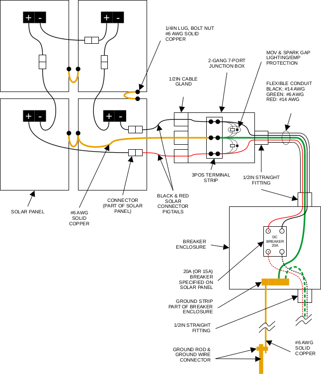
Electrical Installation
Attach the breaker enclosure to the Main Post.
Attach the 7-port junction box to the lower side of the Main Support structure.
Install flexible conduit and conduit connectors between the breaker enclosure and junction box, allowing enough slack for rotation of the Main Support structure.
If the solar panels are exposed to light and connected together in series (or even individual, depending on panel voltage), solar panel wires may conduct high voltage current that could be dangerous. Typically it's best to wait until all electrical components and wiring have been installed before connecting the solar panels.
Attach ground wiring between a terminal strip inside the junction box and the frames of each solar panel (see schematic below). Run ground wire from the terminal strip in the junction box through the conduit and attach to ground strip inside the breaker enclosure. Run bare ground wire from the ground strip out of the breaker enclosure and down the Main Post to a ground rod.
Install a 20A (or 15A, depending on what is required by the solar panel datasheet) inside the breaker enclosure. Install power wiring and lightning/EMP protection between terminal strip lugs and the breaker. Install power and ground wiring between the breaker inside the breaker enclosure and down through interconnect conduit (attached to the breaker enclosure) to the rest of the solar power system (not shown).